
 Daniel Stieler, Phd

A complete solar solution includes a panel, a storage device, a battery, and a charge controller to manage the power generated by the panel and stored in the battery.
At its most basic level, a charge controller maintains your battery’s health and ensures you aren't damaging it. Charge controllers work in several ways to regulate the voltage sent to the battery, and you can throw away enormous amounts of energy if paired with an inappropriate or inefficient controller.
Today we’ll discuss what a solar charge controller is, when and why they are necessary, and compare eight different charge controller technologies, including pulse width modulation (PWM), maximum power point tracking (MPPT), fixed power point tracking (FPPT), direct charging, ratio power point tracking (RPPT), diode-regulated charging, low drop-out regulator charging, and DC-DC converter charging.
To confirm the best controller for your situation, we will focus on each technology’s advantages and disadvantages and why you would want to use each in a specific environment or use case.
Take this blog post with you!
When is a solar charge controller necessary?
This is a common question and one that is crucial. In most cases, you will need a charge controller to charge a battery pack safely. This prevents overcharging and reduction in the battery life of the system. Battery technologies such as Lithium Ion, Lithium Iron Phosphate, Nickel Metal Hydride, or Nickel Cadmium require a charge controller to recharge the battery pack safely (learn more about different battery chemistries, including their benefits and drawbacks). Lead acid batteries are the exception to the rule. Suppose you are trying to charge a lead acid battery quickly or using a large solar module. In that case, you will want a charge controller to keep the battery from overcharging and drying the electrolyte in the battery.
Solar panels used for low current maintenance charging can operate safely without a charge controller if the solar panel output is <1% of the battery capacity.
Solar will cycle on and off each day as the sun rises and falls. As a result, not all charge controllers will be safe for lead acid or AGM batteries if solar is used. Understanding when a charge controller is necessary and what charge controller to pick for a specific application is critical.
Before diving into charge controllers, it is essential to understand that a solar panel in the dark will perform like a diode connected across a battery. This means that any circuit where the solar panel has a direct connection across the battery terminal when it is in the dark will slowly drain the battery. To prevent this, a blocking diode must be placed between the solar panel and the battery, ensuring that current cannot flow out of the battery and into the solar panel.
Solar Charging Methods and Technologies
Direct Charging
Direct charging from a solar panel is possible if you are charging a lead-acid battery. For lead-acid batteries, if the charge current in the battery is less than 1/100th of its amp-hour capacity, it is safe to charge without a charge controller.
For example, if a battery has an 80Ah capacity, then 80/100 = 0.8. This means that the battery can be safely charged using a solar panel that will put in no more than 0.8A at the float voltage of the battery, approximately 13.8V. This is the lowest-cost charging solution, but it does not allow a battery to be charged quickly since only a low-power panel can be used safely.
Additionally, this method is inefficient since the panel will be held at battery voltage and not at its maximum power point. This method works well for systems with low battery load, and the primary goal is maintaining a charged battery during long periods of idle time, like in motor pools.
PWM Charging
This charging method connects and disconnects the panel to and from the battery in short bursts and monitors the battery's voltage to determine the state of charge. The PWM charger will only work with panels with a higher voltage than the battery.
These systems are much less efficient than the DC-DC converter systems because each time the system pulses and connects the battery to the panel, the panel's voltage is set at the battery voltage. Figure 4 shows the percent of maximum power point a solar panel operates at for three controllers, including FPPT, MPPT, and PWM.
The PWM controller can only put 60% to 80% of the peak panel power into the battery. This means that if you have an 18V power point panel, like many of the c-Si panels available on the market, the PWM controller will set the panel voltage at 10.5 to 14.5V, depending on the battery charge level. These voltages are a long way from the power point of the panel, so the power put into the battery from the panel will be much lower than the rated output power of the panel.
![]()
Figure 4: DC-DC converter power point tracking compared to PWM power point tracking.
Power point tracking is essential to maintain the charger's functionality in all lighting scenarios. For example, in the case of a buck converter, if the load draws more current than the panel is actively producing, the high-side MOSFET will turn on and stay on, and the panel will be pulled down to the battery’s voltage. This will result in a significant loss in potential power if the battery’s voltage is far from the panel’s maximum power point.
For a boost converter, if there is not enough power available from the panel, the converter will draw enough current to reduce the voltage below the "on" threshold of the converter and not allow the system to operate. By adding a power point tracking system, these problems can be overcome.
Power Point Solar Charge Controller Options
Power point tracking systems come in three variations: maximum power point tracking (MPPT), fixed power point tracking (FPPT), and ratio power point tracking (RPPT). When selecting an IC that boasts power point tracking, understand your choice. Maximum power point tracking can refer to maximum, ratio, and fixed power point tracking.
Maximum Power Point Tracking (MPPT)
A proper maximum power point tracking system typically has a microcontroller, which implements an algorithm such as “perturb and observe” to identify and maintain the input impedance of the system at the maximum power point for a panel. It works by periodically sweeping the input impedance of the converter and measuring the corresponding change in power.
Are you looking for the best MPPT charge controller that is RF quiet so you can power your ham radio and transmit from anywhere? Check out this video from PowerFilm Solar Ambassador Julian White (OH8STN).
At the end of the sweep, the input impedance of the system is set at the point of maximum power collection until the next sweep is performed. These systems can draw the optimum power from a panel in any lighting condition, including partial shading.
Figure 3 compares the three tracking systems implemented on a solar panel for an indoor IoT application.
![]()
Figure 3: Example of power point tracking systems (yellow line represents the setpoint tracking system set at 2.5V).
Fixed Set Point Tracking (FPPT)
FPPT systems are the least expensive power point tracking systems and work very well when matched to a specific panel and operated in light between 150W/m^2 and 1000W/m^2. They will perform at lower light levels, but due to the panel voltage decreasing as the light level drops, they will run farther from the maximum power point than the other two power point tracking systems.
PowerBoost charge controllers used in PowerFilm’s Soltronix Semi-Flexible Solar Panels are fixed power point DC-DC converters. These systems are designed and optimized to provide the most power from the Soltronix panels they are integrated into at the lowest possible cost providing customers with the best performance and value.
Ratio Power Point Tracking (RPPT)
An RPPT system periodically measures the open circuit (no load) voltage. It sets the input impedance of the converter so that the panel voltage is held at a fixed percentage of the measured open circuit voltage. This system works relatively well and is less expensive than a proper maximum power point tracking system. It works well because as light intensity changes or if an individual cell is damaged or shaded, the remainder of the cells will produce a similar ratio as the entire array. The ratio percentage is specific to solar technology. For example, the ratio for amorphous silicon would be around 0.7, while the ratio for monocrystalline silicon would be 0.8.
Diode Regulated Charging
This charging system uses a Zener diode as the output voltage regulation device to keep the voltage from exceeding a maximum level. One example of a circuit like this is shown in Figure 1. Notice in this system, D1 is incorporated as a blocking diode.
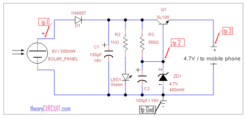
Figure 1: Schematic of a diode-regulated charge circuit. Source: theorycircuit.com
The circuit branch with R2 and the green LED is for indication purposes and is necessary if an indicator is required to show the solar panel is producing some power.
This indicator will turn on even when a solar panel does not produce enough power to charge a device adequately. In some cases, a device may indicate charging due to a charge voltage even though the device is still discharging due to device consumption rates being higher than solar generation rates.
Also, adding indicator circuitry, like an LED, can reduce your overall charge rate. When charging high-power devices like phones, the power consumed by the LED is small compared to device power, but if the same indicator was put on a low-power IoT device, the LED could consume more power than the device itself.
During operation, when the solar panel is illuminated, it will produce a voltage based on the panel type and a current based on the light level. When the output is lower than 4.7V, some of the current produced is consumed by the zener diode, which biases the transistor and allows current to flow into the battery.
As the output voltage rises, the transistor’s effective resistance will increase until the transistor shuts off and battery charging is terminated.
For this circuit to work reasonably efficiently, the solar panel’s power point voltage must be well-matched to the battery or load voltage. The maximum charge current in the battery is controlled by the maximum current produced by the solar panel and is not limited to the circuit.
This diode circuit is an inexpensive option for charging but does not have the efficiency or built-in battery protections of other systems. Extreme care must be taken when using a circuit like this since if one of the circuit elements is incorrect, it could overcharge the battery and damage it or cause a fire. Also, if it is connected to the battery in reverse, it may damage it.
Low Drop Out Regulator Charging
Low Drop Out Regulators (LDOs) can be used for charge controllers on many types of batteries. They work by setting a maximum charge voltage.
These systems are relatively low cost and can be designed to limit the charge current into the battery. Efficiency is low when the voltage of the solar panel is much higher than the battery voltage because the LDO is effectively a variable resistor, so the input impedance is not set to draw power from the solar at the maximum power point.
LDOs charge most efficiently when the solar panel is designed with a power point voltage close to the charging voltage range of the battery. They are also primarily used on low-power systems to manage heat dissipation through the LDO.
Figure 2 shows a TI reference design from the LM1084 LDO datasheet. Using the equation for IF allows the charge current of the system to be calculated and limits set. This system only works for LDOs that are variable voltage output.
Fixed LDOs can also be used to charge a battery but without the ability to control the charge current rate.
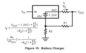
Figure 2: Example of a current-limited LDO charge circuit. Source ti.com
DC-DC Converter Charging
DC-DC converters, Buck or Boost, can be used as battery chargers. These systems offer greater efficiency and an increased feature set. They can be built using either buck or boost reference designs with the addition of power point tracking circuitry or one of the many off-the-shelf ICs with built-in power point tracking circuitry.
DC-DC converters are useful for battery charging across a range of power from microwatts to kilowatts. They come in many different levels of complexity, but to be compatible with a solar panel, they must maintain the input voltage of the panel near its power point.
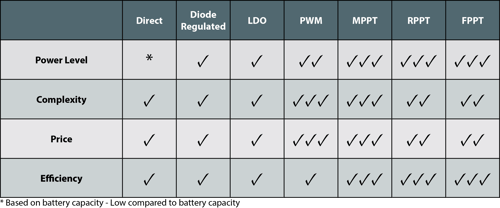
Table 1: Summary of charge controller systems.
Do you need help selecting the right technology for you?
Do you need a solar partner that can provide not only the panel but an integrated charging solution that maintains high performance for a fraction of the price?
PowerFilm is the ideal solar partner, and with our collaborative custom design process, we can help bring your next solar product to market.
Contact us today to start a conversation.
Take this blog post with you!