
PowerFilm has been providing custom solar solutions in the IoT, military, and commercial spaces for over 30 years.
But what does that mean?
Due to the many parameters and complexity of our process, that can sometimes be a difficult question to answer. That’s why we developed a Custom Solar Panel Design Tool to make it easier to understand the different ways we can customize a solar panel.
Walkthrough how to use the design tool with Research & Development Engineer, Sam Jones in the how-to video below.
Right now, the tool remains within the scope of our Electronic Component Solar Panels, which are smaller panels, with few watts that are typically embedded into other electronic applications. However, the same basic concepts apply to all of our product families.
First, you can modify the size and power output of the panel using the “Panel Voltage” and “Panel Current” sections. Then you indicate whether the panel will use indoor or outdoor solar material and finally select any additional custom options that are needed.
Before diving in, let’s briefly go over the basic components of the solar panel that we are modifying.
Basic Anatomy of a Solar Panel
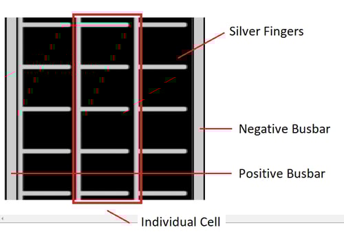
Figure 1
The picture above points out the critical features in a solar panel that will help you understand the customization process.
On the left and right side, we have positive and negative busbars. You can connect to these contacts electrically to extract power from the solar panel.
Between the busbars is the active solar material, which can consist of one or multiple individual solar cells.
Across each cell are silver fingers that collect and carry power through the panel. Silver fingers can help identify busbars since they always point from the positive to negative.
Panel Voltage
We often begin a custom design by defining the needed output voltage. The output voltage is determined by how many cells a panel consists of and whether the solar material is single or tandem junction.
Figure 2 shows how adding cells to the panel increases its output voltage and power, while the current remains the same. Each cell will add 1.2V for tandem junction material and 0.6V for single-junction material.
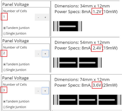
Figure 2
Figure 3 shows the difference between tandem and single junction panels, which otherwise appear identical. A single junction panel will have half the voltage and double the current of a tandem junction panel. Observe that the rated power remains the same. PowerFilm recommends using tandem junction material whenever possible.
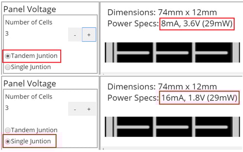
Figure 3
The right output voltage for an application depends on many factors, including your system hardware, charging circuitry, and battery configuration. Please contact us if you need assistance determining the right output voltage for your application.
Panel Current
Once the output voltage is set, you can adjust the size of the cells to match your power needs. Larger cells will generate more current, while smaller cells will generate less. For folks who like equations:
Power [Watts] = Voltage [Volts] x Current [Amps]
We can see that if the voltage is constant, we can increase/decrease power by adjusting the cell size to generate more or less current.
We can change both the length and width of cells. We define cell length across the panel in the direction parallel to the silver fingers. Cell width is defined from top to bottom in the direction parallel to the busbars (perpendicular to cell length).
The right cell length and width depends on the power needs of your application. Adjust both until you reach the desired power/dimensional combination. Please contact us if you need assistance determining the appropriate length/width/power needs for your application.
Cell Length
Figure 4 shows our three standard cell lengths; 10mm, 20mm, and 40mm. As you can see, current and power increase as cells get longer, while voltage remains the same.
Also, note that this isn’t a linear relationship. Larger cells are more efficient since the inactive interconnect space is a smaller portion of the whole panel.
Non-standard cell lengths are possible if necessary, but designing with standard lengths makes manufacturing and prototyping simpler and generally less expensive.
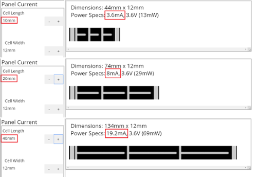
Figure 4
Cell Width
Figure 5 shows how the width of the solar panel can be adjusted. As expected, as width increases, so do the generated current and power, while the voltage remains constant.
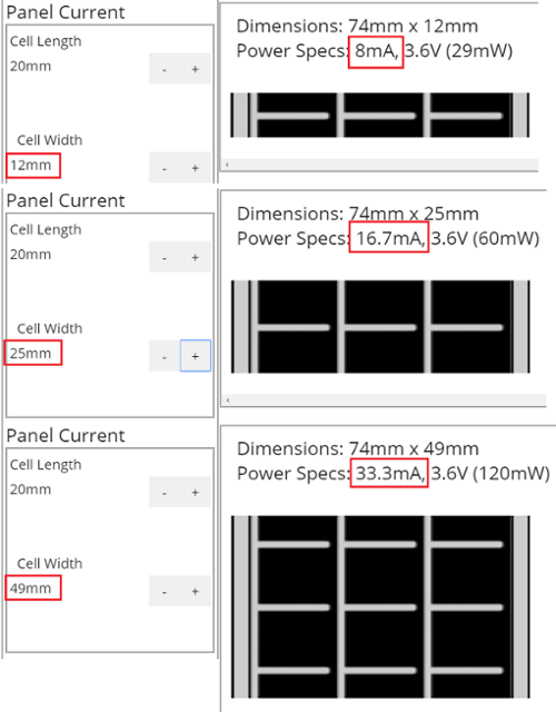
Figure 5
The standard widths available in the drop-down menu are chosen to reduce scrap in our manufacturing process, which uses a 13” wide substrate with 292mm of active area. Therefore, the widest panel we can manufacture without tiling is 292mm, and any width that divides evenly into 292 will not generate scrap.
In general, we can manufacture panels with custom widths anywhere between 10mm-292mm. Designing with standard widths can simplify the manufacturing and prototyping process.
Operating Environment
PowerFilm’s standard material is optimized for bright outdoor environments and is rated for direct sunlight down to 25% sunlight. We also offer indoor solar, which is optimized to collect energy from indoor/artificial light sources.
If your application will be deployed in an outdoor environment, select outdoor. If your application will be deployed indoors, select indoor.
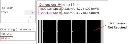
Figure 6
There are a couple of key differences between outdoor and indoor panels. The first is that indoor panels are rated at 200 lux and 1000 lux light levels, instead of 25% sunlight and full sunlight.
Since indoor light is much less intense than direct sunlight, the current generated is also much smaller. It can be more than enough to power a BLE sensor node but probably not enough to charge a cell phone.
Secondly, since power levels are so small, silver fingers are no longer required to carry current through the panel.
If you aren’t sure which material to choose or have a ‘mixed’ use case, please contact us, and we can help work through your application.
Additional Options
There are many additional options available for applications that take advantage of solar.
UV Protection, Weather Seal, Front/Backside Contacts, Black Busbar Tape, Adhesive Backing, Custom Die Cut, and Wide Busbars are just a few examples of common custom options provided to many of our customers.
For outdoor applications, UV protected laminated, and an edge seal process can be used to make the panel stand up against the elements.
Standard panels are completely covered in protective laminate, including the positive and negative busbars. Options are available which remove and expose contact on the busbar to simplify electrical connection. Alternatively, the protective laminate can be removed with mechanical scraping or burned through with a soldering iron.
The tin-plated busbars can be covered in black tape to make their appearance less prominent.
Adhesive options are available for “peel and stick” applications.
Many customers request non-rectangular die-cut shapes. For example, extended tabs can be cut into the bus bar, or the panel can be inscribed in a circular die-cut.
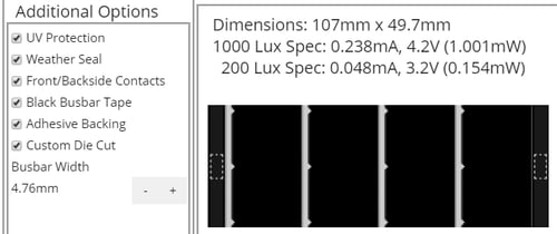
Figure 7
There are many other ways we can customize our solar panels depending on customer requirements and application environments.
Panels can be laminated to various substrates, including metals, fiberglass, fabrics, or other plastics. Connectors and cabling can be added to a design, and charge control circuitry can even be embedded into the panel itself.
We know you’ll find this tool helpful in understanding the way our technology works as well the many ways we can customize a solar panel.
PowerFilm has been providing portable solar solutions for low power electronics for decades. In addition to finding the right solar panel, we can also help customers characterize power requirements, recommend charging circuitry, and make suggestions for power optimization.
If you are interested in learning more about how we provide custom solar solutions, please contact us, and we’d be glad to work through your application.