
Crystalline solar panels are no longer confined to massive solar arrays.
These panels are now more plentiful than ever and come in an endless number of configurations.
There are incredibly inexpensive options that are attractive at first blush, but when you dig deeper the quality of these panels and their assembly process leave much to be desired.
PowerFilm utilizes SunPower cells in our Soltronix crystalline solutions as they are the highest efficiency and most reliable cells available.
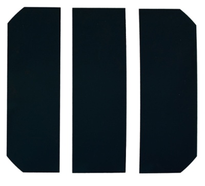
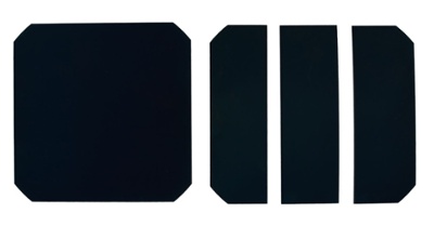
SunPower produces, tests and grades whole solar cells. They do not make 1/2, 1/3 or 1/6 cut cells. Other panel assemblers and third-party companies will take SunPower whole cells and make 1/2 cut, 1/3 cut and 1/6 cut cells.
The disadvantages of using cut cells include loss of efficiency, induced cracks, lower interconnect reliability and lesser long-term stability.
The advantages of using cut cells include flexibility in output voltage and form factor.
The system developed by PowerFilm for using whole cells with its proprietary PowerBoost charge controller eliminates the disadvantages of cut cells while enabling flexibility in output voltage and some limited flexibility in form factor.
Disadvantages of Cut Cells
Loss of Efficiency
SunPower produces a 22% efficient 3.2 watt cell, which is tested before assembly to ensure it meets specification and is well matched in performance to other cells in the panel.
When a solar cell is cut the active area of the cell decreases, due to the kerf (width) of the laser cut, typically 0.05mm. Based on the kerf of the laser used to cut the cell the remaining active area will be about 99.6% of the initial. That reduces cell efficiency from 22% to 21.9%. This is a small decrease, but only the first of several.
For a full cell with two cuts, creating 1/3 cut cells, there will be four defect regions, one on each side of a cut. Taking the 0.05mm *4 for each side of the two cuts the active area is now 99.3% of the total area left. This reduces the cell efficiency to 21.84 %.
Most manufacturers of panels using cut cells actually cut the cell into three equal width pieces and do not account for the area missing due to the cropped corners of a full cell. Since the cells are series connected this creates a current imbalance between cells based on cell active area and limits the power output of the cells to the smallest one. The loss of effective area due to cutting the cells in equal widths instead of equal areas is about 0.9%. This reduces the cell efficiency to 21.64%.
These theoretical losses have proven to be significantly greater in field testing. Measuring the output of each of the 1/3 cells in a solar panel shows that the cut cells produce significantly less power than their equivalent full cell.
On average, a 22% efficient 3.2 watt cell that is cut into 3 pieces will produce about 0.95 watts per piece. If the three pieces are combined back together for an equivalent full cell the output is about 2.85 watts or 89% of the initial power. So, the 22% efficient cell now is about 19.6% efficient.
This is due to both the greater than theoretical losses from the laser cut issues previously mentioned, as well as the redeposition of metal vapor and the lack of retesting and matching cut cell performance to optimize panel performance.
Each of the cells in a panel is connected in series, so the lowest performing cell will limit the current output of the entire array.
Matching cell performance is required to optimize overall panel performance. A weak cell cannot be overcome by putting a few exceptional cells in a series string of cells. A 36 cell string with two to three cells producing less than 0.5 watts cannot be fixed by adding 10 cells producing 1.1 watts.
For example, a 36 cell string of 1/3 cut cells will have a power point voltage of 18V and a power point current of 1.9A, however, if one of those cells is only 0.7 watts the current of the panel would be limited to 1.4A at 18V. At 18V and 1.4A the power is 25.2 watts instead of 34.2 watts. This makes the panel only 14.4% efficient.
If cost is a major concern then a supplier of such panels will receive similar lots of cells and potentially use some lower performing cells in finished panels.
Induced Cracks
The lamination process places extreme pressure on the cells at a fairly high temperature (140-150C). Any edge defect on cut cells can induce a crack during the lamination process.
Most of these cracks are impossible to see with the human eye. Pictures of cracks can be taken by applying a voltage bias to a panel and using infrared imaging.
An infrared picture of a 32 cell panel (purchased online) is shown in Figure 1. This picture shows the defects that were induced mostly during the cutting and laminating process.
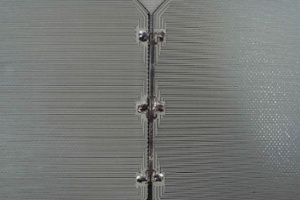
This was a 26 watt panel mounted on a steel frame that produced only about 20 watts at full sun. At 20 watts the panel’s efficiency would only be 16.9%, not 22% as stated on the seller’s website. A picture of a PowerFilm crystalline silicon panel using whole cells is shown in Figure 2.
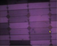
Figure 1: 26 watt panel of 1/3 cut cells. Dark areas show cracks or shorted cells.
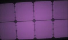
Figure 2: 24 watt whole cell panel, no cracks after lamination.
Interconnect Reliability
A standard SunPower cell has three contact points on each end of a cell. Combined with their patented "dog bone" bus bar connection (pictured below) this has proven to be a very reliable connection, in part due to its redundancy.
When you cut the cells down to 1/2 cells you have 2 connections per cell, at 1/3 and 1/6 you have only one connection per cell. With one connection per cell, if any of the connections fail in the field the entire panel fails.
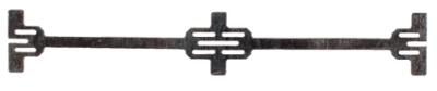
In addition, the SunPower “dog bone” connector is designed to provide a low-stress connection to the wafer and if manufacturers do not use the SunPower "dog bone" then undue stress is placed on the connection, which can increase interconnect failure.
The "dog bone" has cut out reliefs that allow expansion and contraction from cell to cell without adding mechanical stress to the cells contact points.
In addition, 1/2 and 1/6 cut cells will have the one set of contacts cut in half, reducing the size of the soldering pad. Although less critical on 1/2 cut cells this becomes even more significant on a 1/6 cut cell’s interconnect reliability.
Long-Term Stability
SunPower only offers a 25 year warranty on SunPower panels with whole cells.
Besides lamination, the greatest chance for edge defect induced cracks is due to thermal cycling and thermal shock over the lifetime of a panel.
To ensure long-term stability, thermal cycling and thermal shock tests should be performed on cut solar cells.
Cut Cells Boost Panel Voltage
Many companies make panels with cut cells to produce a solar panel at a voltage and wattage that fits the form factor required for the application.
For most 12V battery charging applications you need 15-18V. To reach this voltage with whole cells you would end up with 100-110 watt panel.
For many applications, this is overkill, so by going to 1/2 cut or 1/3 cut cells the power can be cut by a similar amount.
A cut cell enables a company to make a smaller solar panel at a higher voltage to meet a particular need; however, the combinations are somewhat limited.
PowerBoost Boosts Voltage Electronically
Crystalline panels now litter the internet with prices that continue to plummet.
Before saddling yourself to an assembler it is vitally important to consider standard assembly processes.
Creating an efficient and reliable solution that will deliver for years to come is the result of being intentional and utilizing the highest quality cells and engineering.
By designing PowerBoost, a boosting charge controller, compatible with low voltages, PowerFilm is able to leverage the advantages of panels made with whole cells at lower panel wattage and smaller form factors.
This yields a superior integrated product that meets power and form factor requirements other manufacturers can only meet with less efficient, riskier cut cells.
Interested in learning more about our custom solutions?
Contact us and let’s start a conversation today.