Integrating solar panels into a printed circuit board can make life a lot easier for product designers.
In our last post, we walked through the various methods you can choose to make a connection (read the post here).
What if the product design you are working on requires a PCB to be flexible?
Luckily flexible PCBs are becoming more and more popular, and thin-film solar is the ideal flexible power source.
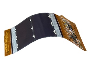
PowerFilm’s thin-film amorphous silicon (a-Si) solar modules are ultra-thin, flexible, and can take the form of whatever the module is attached to.
Take this blog post with you!
%20solar%20panel%20flexing.jpg?width=243&height=192&name=amorphous%20silicon%20(a-si)%20solar%20panel%20flexing.jpg)
Flexible circuit boards share this property, making them an excellent match for thin-film flexible solar modules.
Mounting a solar module to a flex board increases the durability while allowing the user to attach extra circuitry to the panel’s backside, along with many other benefits.
In this post, we will discuss what is necessary to attach a solar module to a flexible pc board, the benefits of flexible pc boards, and a few reasons why a flexible pc board might not be a good fit for specific applications.
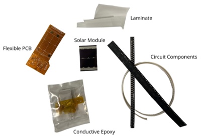
What is needed to attach a solar module to a flexible PC Board?

- Solar module (in this case the LL200-2.4-37)
- Flexible circuit board
- Conductive epoxy
- Additional circuitry (Optional)
- Laminate (Optional)
The solar module can be attached using the conductive epoxy method described in our last blog post.
Why use a flexible circuit board?
Variable form factor
A flex PCB will be much thinner and lightweight than a typical rigid PCB. This allows it to conform to whatever shape it is placed in or around, making it perfect for applications that require bending around a radius.
These applications include wearables and many other compact internet of things devices. Using a flexible PCB allows designers to put backside contacts anywhere on the back of the solar module by rerouting the power and ground lines away from the copper tape.
The circuitry can be laid out using the flexible PCB on the side opposite of the solar module, allowing designers to only worry about one circuit board if the design is small enough.
Durability
A solar module mounted to a flexible printed circuit board using conductive epoxy can bend a 1-inch radius repeatedly for at least 10,000 flexes before failure.
Connectors, whether they be screw terminals or FPC connectors, can wear out or become disconnected with repetitive bending.
If increased flexure endurance is required, glue dots on the back of the module or laminating the FPC are solutions (read about the importance of lamination and different options).
Cost
While the cost of prototyping a flexible printed circuit may be higher than a rigid PCB, in quantity, it is possibly cheaper due to the lack of interconnects, depending on the size of the flex circuit board.
Cost can be reduced further by attaching the solar module to the FPC using a pick and place machine and a stencil for the conductive epoxy.
If possible, circuits can be designed on the backside of the FPC to reduce the circuit board’s footprint and cost.
Downsides
There are a few downsides to using a flexible circuit board.
Conductive epoxy makes switching to a different sized panel difficult without a board redesign.
The cost of the FPC may not be viable if the physical size is too large, if there are too many features, or if the quantity ordered is too low.
Flexible circuit board layouts also have different design rules than rigid PCBs, which may disallow smaller parts.
Flexible PCBs and flexible solar modules can be a perfect match if durability or bending ability is necessary while keeping the overall design footprint compact.
Are you interested in a new design incorporating our flexible solar?
Are you upgrading a previous design?
Contact us, and we can assist with a custom solution for your product!
Take this blog post with you!